Spicycle for engineering design
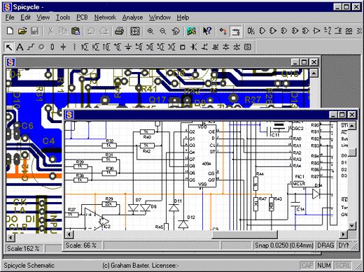
Spicycle is now our leading Engineering Design product. It provides an easy to use schematic front end to our well established network simulator. Spicycle includes the facility to design and lay out printed circuit boards directly from netlists and schematic diagrams. Since all the processes are controlled using Active X, you get automatic back annotation between schematics, netlists and simulation settings.
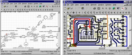
As well as being a first class drawing and electronic design tool, the new schematic features allow you to design and simulate a whole range of other Engineering Systems - one of our customers uses Spicycle to design Tunnel Ventilation systems!
PCB layout
You are placing yourself among the leading electronic designers in the world by using Spicycle. Absolute control over the tracks is vital for analogue circuits and you can be confident that the clear tracks and pads you see on screen are those you are going to get. Uniquely, you can test your PCB directly on the simulator.

Quality assurance
The region-based Design Rule Checker will check that your high voltage tracks comply with the standards, that high frequencies are well separated from interfering signals and that less demanding circuits are made as compact as possible. A broken-net facility highlights potential faults. Of course, the simulation facility not only provides the ultimate in pre-build testing but its net list records the component build items.
Spicycle is a studio of facilities
It is a 2D drawing program with a range of tools ready made for drawing schematic diagrams of electronic and other engineering schematics. It is a 2D drawing program with a range of tools ready-made for drawing and outputting PCB layouts. Underlying its drawings is a dynamic data base that creates a net list in real time instantly ready for simulation.
It offers mixed-mode simulation (connecting transparently to SpiceAge). Data flow to its data base is fully bi-directional with the drawings: this means that you can import a SPICE netlist and it will present you with the corresponding schematic symbols ready-connected: it also means that back annotation with simulation settings comes for free.
Supporting the concept of data interoperability, Spicycle’s Active X controls provide flexible interaction with other modern Windows programs and fully supports the standard OLE functions. This means, for example, that you can edit drawings built into your Word documents using the familiar Spicycle tools.
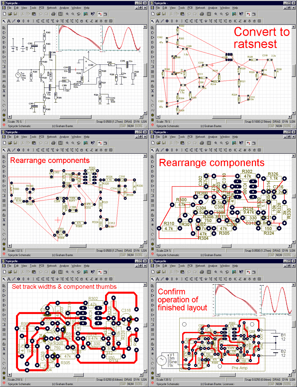
Such is the integration between facilities that you can connect hook-up wires from the terminals of your PCB to a schematic of a function generator and have the PCB circuit simulated directly. And to reinforce your confidence that nothing has been wrongly connected, Design Rule Checking and a Broken Nets highlighting facility are also available.
Validating
Spicycle connects to advanced mixed-mode simulation. Here, you can investigate tolerances (Monte Carlo analysis), tune component values using sweeping functions, check filter suppressions (better than 300dB resolution Fourier analysis) and test your circuit on a whole range of inputs (including those grabbed from a SoundBlaster compatible card). You can even output results to a SoundBlaster card and listen to your design. Spicycle’s simulator is independent of SPICE even though it is backwards compatible. This means that your safety-critical systems can be independently validated by connecting Spicycle to a third party SPICE simulator.
Integration for integrity
Such is the integration between facilities that you can connect hook-up wires from the terminals of your PCB to a schematic of a function generator and have the PCB circuit simulated directly. To ensure that nothing has been wrongly connected, Design Rule Checking and Broken Nets highlighting are available.
Here is a little preamplifier circuit to show how you can use this integration to good advantage.

.jpg)
.jpg)
